LOWER PAN

This part forms the contour of the lower shroud
LOWER PAN

Here I have installed nutplates to attach the shroud along the lower edge.
LOWER PAN

Another view.
Beginning

Made a hammerform to shape the upper pan, which also is a tool tray. This allowed me to hold the shape I wanted for the main body.
Beginning

Another view. I needed to trim the lower edges and corners, as well as form a flange along the left and right vertical edges.
Another View

Working on the depth of the major portion.
Another View

I will use the center of the water pump to determine the location and size of the fan cutout. You must have the shroud set in place so your center does not change.
Before the cut
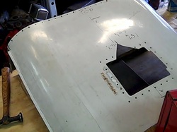
This used to be a jet engine cowling. The square with all the holes around it was the oil fill door. This will be cut out.
Side view

You can see the hammerform under the shroud. There ar 2 pieces of plywood that make up both sides of the hammerform.
Cutout

The hole has been cut. I hammerformed the edge of the hole, to eliminate some of the "boing" in the metal, as well as adding a little reinforcement.
Cutout

No fan spacers needed.
Progress

I have compensated for 1/4 inch clearance all around the fan itself, for radiator movement. The engine is solid mounted, the radiator has original GM rubber mounts incorporated in the radiator supports. I had to plan and design the rad support structure to incorporate using the GM mounts.
Layout

You can see the lower cap and how it is attached to the shroud.
Lower Cap
Lower cap in position. It is held in place by a strip that is attached to the lower rad support. You can see the GM rubber mount by the upper black clamp .
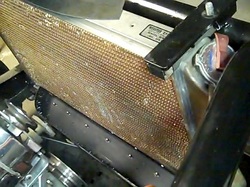
Test fit
With every step, I had to test fit the shroud. Here I added some swirl polished aluminum, which I acquired from someone.
Sidw View

Since rad and engine are each tilted a few degrees, the aft edge of the flange needs to be trimmed to the same rotating plane as the fan. All radiators should be mounted at a very slight angle, so the air passing through it has something to rub against to remove heat from the fins.
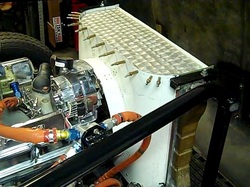
Getting somewhere.....

Here you can see my idler pulley and self fabricated alternator mount. I always try and get the alternator mounted as close as possible to the other pulleys. I do not have a serpentine setup. I am old school.
Paint

After riveting everything together, some paint was applied to seal it and prevent corrosion.
Installed

Another view.
Tool Tray

Tool tray in use.
Left side view

Here you can see the orange rub strip between the shroud flange and the rad fins. Also note my deep groove idler pullet setup-keeps the belt on at high RPM's
Done

I love my tool tray. Perfect example of form and function. This engine should stay pretty cool.
